Dies ist eine alte Version des Dokuments!
UI Board Test & Fehlersuche
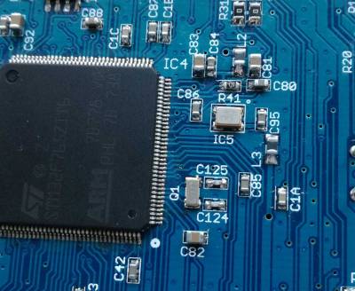
die MCU hat zwei (!) Pin 1 Markierungen
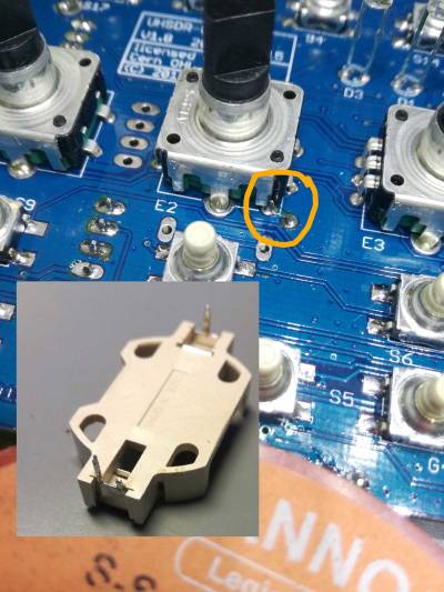
Note: Also ganz wichtig: Wie auf dem Bild zu sehen unbedingt den einen Anschlußpin vor dem Einbau kürzen/abschneiden.
Note: Achtung: die MCU hat zwei (!) Pin 1 Markierungen
Im falle von fehlendem Audio out: just in case, please check the SW_12V connection. This is power supply connector for Audio power amplifier stage unlike the mcHF.
Typischer Stromverbrauch: mit Display 280mA und ohne Display sind es 190mA. Die 80mA waren ohne Display direkt nach der Inbetriebnahme.
Flashprobleme:
- Uhrenquarz und TCXO sind für das Flashen beide absolute Voraussetzung.
- Bitte genau prüfen ob der TCXO richtig herum eingelötet ist!
- wenn die 3V3 am C95 nicht mehr anliegen ist L3 wohl defekt
Helle LEDS: Mit den Bausatz-Vorwiderständen leuchten die LEDs sehr hell. DF9EH hat die Werte reduziert:
- R36 auf 22,6k (D1 grün)
- R37 auf 6,8k (D2 rot)
- R116 auf 6,8k (D3 blau)
MCU wiederbeleben ("un-brick")
Eine nicht mehr funktionierende OVI40 MCU kann - sofern es sich um keinen Hardware Defekt handelt - auf 3 Wegen wiederbelebt werden:
- via USB-Stick (.bin-Datei)
- via DFU und USB-Kabel (.dfu oder .bin - in letztem Fall musst Du die Startadresse mitgeben 0x810000)
- via ST-Link (.bin-Datei - auch hier musst Du die Startadresse wie bei 2) angeben)
Die Dateien dazu finden sich hier:.
You will need : - an up to date STM32 ST-LINK utility ( http://www.st.com/en/development-tools/stm32-programmers.html?querycriteria=productId=LN2013 ) running on something (you choose) - a ST-LINKV2 probe ( http://www.st.com/content/st_com/en/products/development-tools/hardware-development-tools/development-tool-hardware-for-mcus/debug-hardware-for-mcus/debug-hardware-for-stm32-mcus/st-link-v2.html ), (you might use some other compatible hardware) - latest version of the Bootloader and/or UHSDR Firmware
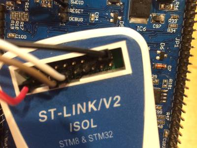
The only tricky part is to connect the probe JTAP connector to the JP8 UI board, here are the needed wires :
JP8-3 (SWDIO) to JTAG-7 JP8-4 (SWCLK) to JTAG-9 JP8-5 (UI_3V3) to JTAG-1 JP8-6 (GND) to JTAG-20
The rest of the procedure is straight forward : connect, erase, flash and you are done.
One additional trick, when I first connected to the MCU, I got an error message « Readout Protection Mode » and was unable to erase the chip. I finally choosed to try to flash a first time and the utility did what was necessary to remove the protection mode. Cool, thank you STM !
A couple of us faced the same issue during beta testing the new UI board. But as you could see a cheap chinese ST Link adapter from Amazon or eBay saves your day
Here are the steps. Unfortunately in German but maybe it helps. https://www.amateurfunk-sulingen.de/forum/index.php?board=15;action=display;threadid=577;start=315 Register values from Andreas: https://www.amateurfunk-sulingen.de/forum/index.php?board=15;action=display;threadid=577;start=285
The URLs are from a (forgotten) I40 UI thread in the mcHF folder.


