UI Board Test & Trouble Shooting
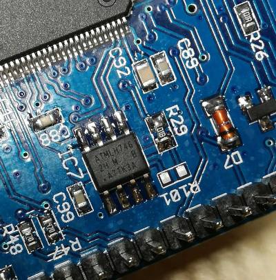
EEPROM IC7 Pin 1 orientation
This is where the dot is printed. Also the edge of the case is slanted near the 1-4 pins. See here
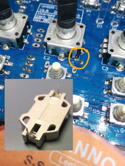
Potential short cut next to battery holder
Note: Also ganz wichtig: Wie auf dem Bild zu sehen unbedingt den einen Anschlußpin vor dem Einbau kürzen/abschneiden.
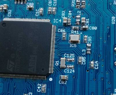
Attention: STM32 MCU Pin1 Mark
The MCU seems to have two (!) pin 1 marks. Watch text orientation on MCU to find “real” pin 1.
Missing Audio out
In case of missing audio out: just in case, please check the SW_12V connection. This is power supply connector for Audio power amplifier stage unlike the mcHF.
Typical current consumption
Typischer Stromverbrauch: mit Display 280mA und ohne Display sind es 190mA. Die 80mA waren ohne Display direkt nach der Inbetriebnahme.
In case of problems to flash the MCU
- RTC clock crystal and TXCO are prerequisite for flash programming to work
- Check correct orientation of TXCO (see photo on this page)
- Check 3.3V at C95. If not present then L3 may be defective
LEDs too bright
With the kit resistors the LEDs are quite bright. DF9EH has reduced the values as follows:
- R36 22k6 (D1 green)
- R37 6k8 (D2 red)
- R116 6k8 (D3 blue)
"WM8731 not detected"
In case you see this UHSDR error message please check +3V supply for codecs (WM8731) is ok. This +3V supply is generated on RF board.
MCU does not work, DFU connection / DfuSe not working also
First check that MCU is soldered in in correct orientation (see above “Pin 1”).
In order to boot the MCU needs:
- CPU clock (→ check TXCO clock)
- correct reset voltage over time at boot up (→ check voltage over time, check voltage levels at reset pin of MCU)
Only if thos pre-conditions are met will the MCU work with DfuSe or ST-Link/V2 and closed jumper “P6”.
Only after bootloader starts correctly will pin voltages for switches, LEDs and LCD be initialized to some extend., e.g. “Band+” and “Band-” switch.
Also check:
- Does PC recognize the OVI40 UI board connected via USB cable, as USB device in device manager?
- PC USB port working? USB cable ok?
- Check all MCU pins are correctly soldered and no shortcuts exist: Use a thin knife / scalpell / tweezer, go inbetween MCU pins and try to push the pins gently sideways one by one, check if all are soldered to PCB. If not the pin moves slightly.
USB Stick does not work
Please check +8V supply from Rf-Board, JP1.


