Display Test & Trouble Shooting
Note: If not noted otherwise: All texts in this page relate to 3.5 inch display.
Display or Firmware Problem?
In case the display doesn't work (white screen) the following is suggested to find out if it is a SW or HW problem:
- Plug 3.2“ Display into OVI40 UI (if available) and load firmware. In case this display works: switch of UI board, unplug 3.2” display and insert 3.5“ display board into UI. Now power up UI again. If LCD screen shows expected UHSDR display in upper left corner then it is not a HW problem. on the LCD board.
In case of a suspected HW problem: check all connections for potential short-cuts e.g. to ground, or possible interruptions. Also check the flexible cable (flexible PCB) of the LCD. This may be damaged and defective.
Possible reasons for "white screen"
- bad soldering points or shurtcuts on the LCD's FPC connector
- bad soldering points or short cuts at IC103
- forgot to insert jumper at R10
The soldering points on the FPC connector or the connector itself may be damaged by excessive soldering time or heat. To check contact problems on FPC connector: pull flatband cable out of connector sufficiently so that a measurement tip can just about touch the copper contact noses, then check for short cuts and continuity. Especially check for short-circuits to the next contact left or right of the one you actually check with the tip.
There are exactly 3 places where it is correct to have short circuits (please also refer to schematics):
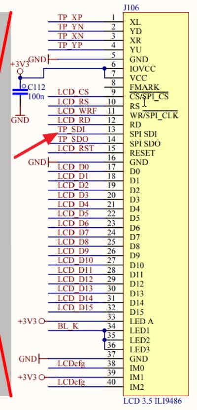
- the parallel LED connections (LED1 LED2 LED3 - see display interface description on this page)
- next to that there are two parallel ground connections next to each other
- the two coding lines IM0 and IM1 are also connected in parallel
Any other short-cuts need to be repaired and removed.
Firmware now adapts dynamically to LCD size and type
Starting with firmware 2.7.74 the FW contains drivers both for ILI932x LCDs (old 2.8” LCD, 3.2“ LCD) @320×240 as well as ILI9486 (for new 3.5” LCDs) @480×320. The firmware now automatically detects which controller is present and auto-configures respectivelly. The 480×320 LCDs will give a much sharper display - important for waterfall and spectrum display - over the whole display area.
Test if U103 is OK
- unsolder U 103
- short-circuit Pin 3 and Pin 4 on PCB (where U103 was previously)
This can be used to exclude a defective U103 (or one that has been soldered in in wrong orientation).
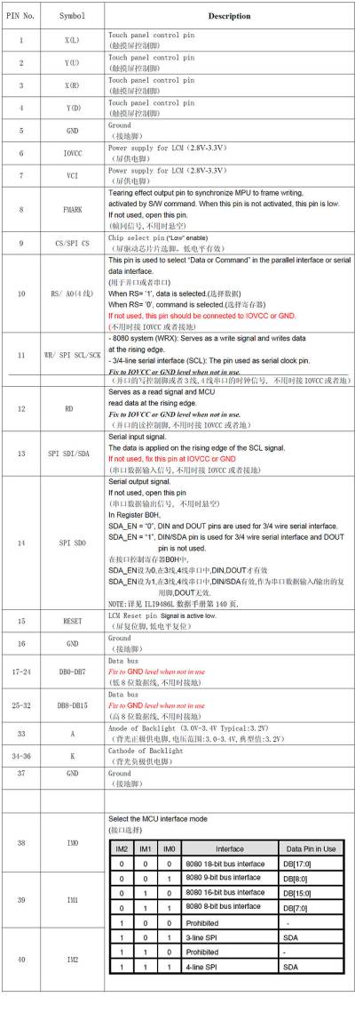
LCD interface and display controller
For information and trouble shooting:
Note: ToDo move jpgs into correct name space

