Ceci est une ancienne révision du document !
OVI40 - déscription brève
Modules OVI40-SDR
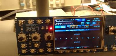
Le OVI40-SDR est composé des modules suivants: * Module OVI40 UI * Module LCD avec écran tactile * Module RF board * Casier
Module OVI40 UI
Module OVI40 UI:
| Dimensions de la carte: | 186mm x 66mm |
| Processeur: | STM32F76x (Horloge 216 MHz), STM32H743ZIT6 en option (Horloge 400 MHz, broche compatible avec STM32F76x) |
| Codec audio: | 2 x WM8731 @ 96KHz (UHSDR utilisant actuellement 48 kHz seulement), IQ et Audio séparés (TX et RX possibles simultanément, la carte RF doit supporter ceci) |
| Affichage: | 3.5 “480 × 320 par défaut, 3.2” et 2.8 “pris en charge |
| Interface LCD: | parallèle et SPI pris en charge, parallèle utilisé par défaut |
| Mémoire interne: | SPI-Flash (Option), SPI-RAM (Option) |
| Mémoire externe: | carte microSD |
| Horloge en temps réel: | partie Realtime Clock (RTC) intégrée du STM32 MCU, pile de secours CR2032 |
| LEDs: | 3 |
| Connexions externes: | Mini-USB Type B, USB-Host (USB-A), connecteur 3,5 mm pour microphone et PTT, connecteur 3,5 mm pour entrée analogique, connecteur 3,5 mm pour sortie analogique (sortie ligne indépendant du haut-parleur), connecteur 3,5 mm pour casque |
| Connexions internes: | Connecteur 30 broches (compatible carte RF mcHF), GPIO 6 broches, connecteur 25 broches (GPIO, SPI, I2C), connecteur Debug compatible ST-Link V2, sortie de débogage, 2 connexions USB internes 4 broches |
| Touches: | 18 touches séparées |
| Codeurs rotatifs: | 4 codeurs rotatifs avec fonction de touche intégrée |
| Sortie audio: | Stéréo, 2 x 3W à 2 x 4 Ohm avec moins de 1% THD + N |
L'en-tête 30 broches J1 est compatible avec les cartes RF mcHF jusqu'à la carte RF V0.6 incluse. Les cartes RF OVI40 UI et mcHF peuvent être utilisées ensemble. Une carte RF OVI40 améliorée est en cours de développement.
Tableau d'affichage
Note: ToDo Photo </ bootnote> <95% 15% 80%> |
| Taille de l'écran: | 3,5 pouces |
| Type d'affichage | TN |
| Résolution: | 480 x 320 |
| Contrôleur: | ILI9846 (et compatible) |
| Interface humaine: | Écran tactile |
| Interface: | SPI et Parallèle |
2,8 pouces ou 3,2 pouces 320 x 240 Écrans tactiles mit IL9325 (ou compatible) contrôleur peut également être utilisé.
Conseil RF
<bootnote> ToDo Photo et tableau de données </ bootnote>
Logement
<bootnote> Texte et données de ToDo GHousing </ bootnote> OVI40 ne s'adaptera pas aux boîtiers mcHF actuels. Contrairement à la mcHF, les cartes RF OVI40 seront équipées de cartes PCB supplémentaires. On suppose que ces cartes d'adaptation peuvent mesurer jusqu'à 5 cm de long. Il y aura des boîtiers spécifiques OVI40 développés et fournis qui ne veulent pas construire leur propre logement. Ces boîtiers seront développés après la finition de l'OVI40.
OVI40 Short Specification
OVI40-SDR Components
The OVI40-SDR consists of the following components:
- UI Board
- Display und Touchscreen Module
- RF Board
- Housing
UI Board
UI board table of features:
| PCB Dimensions: | 186mm x 66mm |
| Processor: | STM32F76x (216 MHz Clock), optional STM32H743ZIT6 (400 MHz Clock, pin compatible with STM32F76x) |
| Audio Codec: | 2 x WM8731 @ 96KHz (UHSDR currently using 48 kHz only), separate IQ and Audio (TX and RX possible simultaneously, RF board needs to support this) |
| Display: | 3.5” 480×320 as default, 3.2“ and 2.8” supported |
| LCD Interface: | parallel and SPI supported, parallel used as default |
| Internal memory: | SPI-Flash (Option), SPI-RAM (Option) |
| External memory: | microSD card |
| Realtime clock: | integrated Realtime Clock (RTC) part of STM32 MCU, CR2032 Backup Battery |
| LEDs: | 3 |
| External connections: | Mini-USB Type B, USB-Host (USB-A), 3.5mm connector for microphone and PTT, 3.5mm connector for analog input, 3.5mm connector for analog output (line-out is independant from loudspeaker), 3.5mm connector for headset |
| Internal connections: | 30pin connector (mcHF RF Board compatible), 6pin GPIO, 25pin connector (GPIOs, SPI, I2C), ST-Link V2 compatible Debug connector, Debug output, 2 x 4 Pin internal USB connections |
| Keys: | 18 separate keys |
| Rotary encoders: | 4 rotary encoders with integrated key function |
| Audio output: | Stereo, 2 x 3W at 2 x 4 Ohm with less than 1% THD+N |
The 30pin header J1 is downward compatible with the mcHF RF boards up to and including RF board V0.6. OVI40 UI and mcHF RF board can be used together. An improved OVI40 RF Board is in development.
Display Board
<bootnote>ToDo Photo
| Display size: | 3.5 inch |
| Display Type | TN |
| Resolution: | 480 x 320 |
| Controller: | ILI9846 (and compatible) |
| Human Interface: | Touchscreen |
| Interface: | SPI and Parallel |
2.8 inch oder 3.2 inch 320 x 240 Touchscreen Displays mit IL9325 (or compatible) controller can also be used.
RF Board
Note: ToDo Photo and Data table
Housing
Note: ToDo GHousing text and data
