peter_77
Urgestein

 Offline Offline
Posts: 735

THE mcHF and UHSDR forum !


|
 |
Re:Aufbaubericht OVI40-UI Platine Version 1.8
« Reply #90 on: 15. January 2018, 08:25:05 »
|
|
| Dfuse hat das Board über USB immer noch nicht erkannt. |
|
Nur mal nachgefragt:
Band - hast du dazu gedrückt wenn du die 5V ans UI anlegst ?
Sonst geht es nicht und der USB Port erkennt KEIN STM Device in DFU Mode
|
|
 Logged Logged
|
|
|
|
DG2NPE
noch länger dabei
Offline
Posts: 135

Ich liebe dieses Forum!
|
|
Re:Aufbaubericht OVI40-UI Platine Version 1.8
« Reply #91 on: 15. January 2018, 09:50:14 »
|
|
Vielen Dank für die Tipps,
Habe alles nach 'Vorschrift' ausgeführt. Beim Start wurde Version.. 61 angezeigt. Unter DFU war dann die Version.. 63 möglich.
Werde mal suchen, wo meine Fehler liegen. Eure Tipps grenzen das ganze etwas ein.. .
73 Peter, DG2NPE
|
|
Logged
|
|
|
|
S53DZ
schon länger dabei
Offline
Posts: 58
Ich liebe dieses Forum!
 
|
|
Re:Aufbaubericht OVI40-UI Platine Version 1.8
« Reply #92 on: 15. January 2018, 10:30:14 »
|
|
Hallo Peter,
I did it this way:
(0.) Use DFU mode (J6) to load the newest F7 bootloader (bl-40SDR.dfu)
1. +8V on JP1 pin 29 - to power the USB stick!
2. Press and hold! BAND -
3. +5V on JP1 pin 28 - to envoke bootloader
4. Put USB stick into USB port - with the appropriate name of FW (fw-40SDR.bin)
5. Wait for it to finish FW upload
6. Release the BAND -
7. Power cycle +5V
Et voila.
I hope this helps you to get thru.
73 Bojan
|
| « Last Edit: 16. January 2018, 10:02:42 by S53DZ » |
Logged
|
|
|
|
DG2NPE
noch länger dabei
Offline
Posts: 135
Ich liebe dieses Forum!
|
|
Re:Aufbaubericht OVI40-UI Platine Version 1.8
« Reply #93 on: 15. January 2018, 10:59:28 »
|
|
Schande über mein Haupt. .
Dachte, wie im Plan, Masse liegt immer auf der gleichen Seite. . LED's verpolt eingebaut. .
Jetzt gilt es den Rest zu finden - 500 mA für das UI.. .
@Bojan: Thanks for Your Tips!
73 Peter, DG2NPE
|
|
Logged
|
|
|
|
db9mat
noch länger dabei
Offline
Posts: 104
Ich liebe dieses Forum!
|
|
Re:Aufbaubericht OVI40-UI Platine Version 1.8
« Reply #94 on: 15. January 2018, 11:30:40 »
|
|
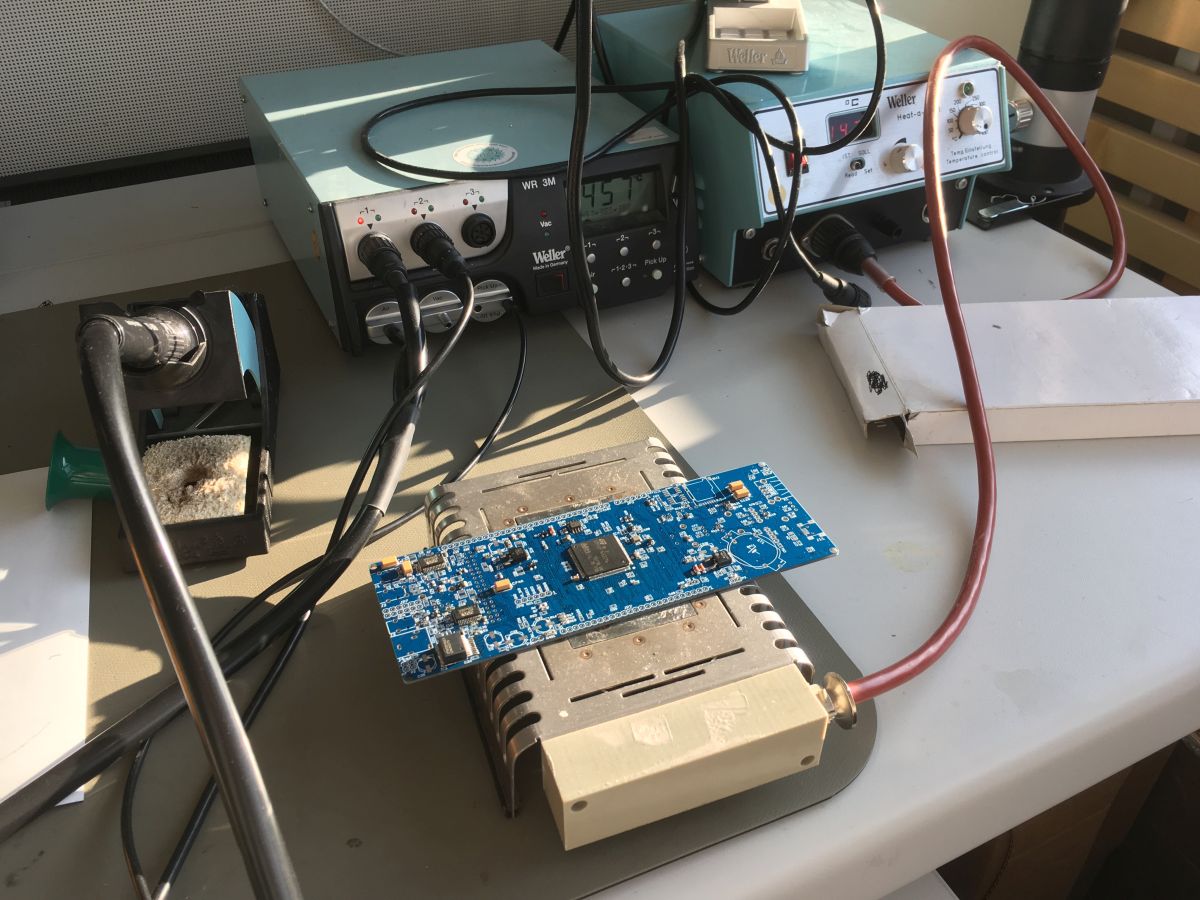
So, Operation STM drehen erfolgreich gelöst. Heizplatte, Heißluft und Vakuumpinzette ist schon was tolles..  Mit etwas Paste in den Ofen, da ich Angst hatte, dass beim Handlöten das ein oder andere Pad dran glauben müsste. Hat gut geklappt, die paar Kurzschlüsse ließen sich wunderbar mit Litze entfernen. Und ja, die Flussmittelreste kommen noch runter. Mit etwas Paste in den Ofen, da ich Angst hatte, dass beim Handlöten das ein oder andere Pad dran glauben müsste. Hat gut geklappt, die paar Kurzschlüsse ließen sich wunderbar mit Litze entfernen. Und ja, die Flussmittelreste kommen noch runter.
Bilder von der Operation gibts hier: https://imgur.com/a/xyZk0
|
|
|
|
DL8EBD
positron
Urgestein
Offline
Posts: 1908
|
|
Re:Aufbaubericht OVI40-UI Platine Version 1.8
« Reply #95 on: 15. January 2018, 11:38:24 »
|
|
danke für die Bilder.
Es geht nichts über gutes Werkzeug 
|
|
Logged
|
|
|
|
dg0nf
OM_nicht_I40
noch länger dabei
Offline
Posts: 132
OV V30 - Wolgast/Insel Usedom
|
|
Re:Aufbaubericht OVI40-UI Platine Version 1.8
« Reply #96 on: 16. January 2018, 09:52:50 »
|
|
Moin Allerseits!
Seit heute funktioniert mein OVI40-UI-Board auch komplett.
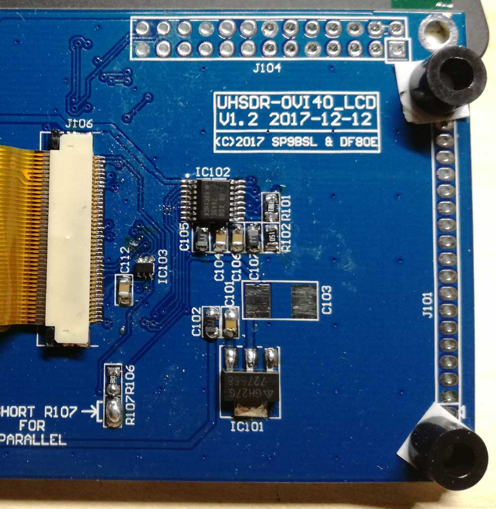
Ich hatte beim Zusammenbau des Displays den FPC-Steckverbinder gekillt (eine Seite von der grauen Verschlussschiene abgebrochen, weil die sich irgendwie verkantet hatte), damit kontaktierte der Steckverbinder das Display nicht mehr richtig und es blieb dunkel. Ich hab dann im Lager nachgesehen, hatte zwei verschiedene Sorten 40pol FPC-Verbinder mit 0.5mm Pinabstand da. Also, alten Steckverbinder runter, neuen Steckverbinder drauf und erst dann festgestellt, dass der von unten kontaktiert und nicht von oben, wie der, der original drauf war.. Die zweite Version im Lager kontaktiert genau so. Andreas war so freundlich und hat mir auf die Schnelle einen neuen FPC-Verbinder geschickt, den ich heute eingelötet habe.
Firmware hatte ich letzte Woche schon aufgespielt und so musste ich heute nur noch den Test mit Display durchführen, was dann auch sofort funktionierte
Test mit RF-Platine steht noch aus, die ist im Moment noch am mcHF und der liegt zu Hause.
Gruß, Helge
|
|
Logged
|
|
|
|
db9mat
noch länger dabei
Offline
Posts: 104
Ich liebe dieses Forum!
|
|
Re:Aufbaubericht OVI40-UI Platine Version 1.8
« Reply #97 on: 16. January 2018, 19:26:17 »
|
|
Soo, meine UI Platine tut auch seit heute. Eigentlich alles ganz straight forward.
Wie ist eigentlich der Plan für die Befestigung der LCD-Platine? Die Löcher sind ja verdeckt und nur an dem 2x20Pinner wackelt es ganz schön..
|
|
Logged
|
|
|
|
|
|
DL8EBD
positron
Urgestein
Offline
Posts: 1908
|
|
Re:Aufbaubericht OVI40-UI Platine Version 1.8
« Reply #99 on: 16. January 2018, 19:32:43 »
|
|
gute Frage, da habe ich auch noch keine brauchbare Lösung.
Ich werde wohl im QRL ein Stück Pertinax sägen und links aufkleben damit das Display da drauf ruhen kann.
Andreas schrieb mal was von einem passenden Folienkondensator 
|
|
Logged
|
|
|
|
db9mat
noch länger dabei
Offline
Posts: 104
Ich liebe dieses Forum!
|
|
Re:Aufbaubericht OVI40-UI Platine Version 1.8
« Reply #100 on: 16. January 2018, 19:55:39 »
|
|
Au ja, die Idee gefällt mir )
|
|
Logged
|
|
|
|
DF9EH
alter Hase
Offline
Posts: 284
|
|
Re:Aufbaubericht OVI40-UI Platine Version 1.8
« Reply #101 on: 16. January 2018, 21:24:54 »
|
|
Ich habe auf die Schnelle zwei Plastik Abstandshalter von 5mm Höhe mit doppelseitigem Klebeband auf die Platine gepappt ....

|
|
Logged
|
73 de Klaus
|
|
|
DF9EH
alter Hase
Offline
Posts: 284
|
|
Re:Aufbaubericht OVI40-UI Platine Version 1.8
« Reply #102 on: 16. January 2018, 21:33:51 »
|
|
Hier ist noch ein Bild von dem Teil:
|
73 de Klaus
|
|
|
DL8EBD
positron
Urgestein
Offline
Posts: 1908
|
|
Re:Aufbaubericht OVI40-UI Platine Version 1.8
« Reply #103 on: 17. January 2018, 05:41:34 »
|
|
Vorschlag für eine UI Revision V1.9
korrespondierend zum J101 des Displayboards auf der UI ein paar Lötaugen vorsehen.
Es sollten je zwei an den Rändern ausreichen.
2polige Buchsen in die UI und 2polige Stiftleisten ins Displayboard.
Sitzt stabil und ist (bleibt) ohne Kraftaufwand steckbar
|
|
Logged
|
|
|
|
SP9BSL
positron
alter Hase
Offline
Posts: 443
|
|
Re:Aufbaubericht OVI40-UI Platine Version 1.8
« Reply #104 on: 17. January 2018, 06:56:18 »
|
|
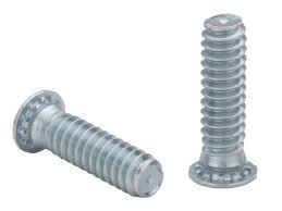
Hi,
I have other options which are already available (lcd board was designed to this):
1. Use a plastic hex shape spacer with external/internal thread like this one:
https://www.tme.eu/pl/details/tp-11/tuleje-dystansowe-plastikowe/fixfasten/
by putting the externally threaded part of it into available 3mm hole in lcd board, cut out the excess and simply glue it to the pcb.
Yes- in the future revisions of UI we should have two 3mm holes to lcd screwing, but for now it will be sufficient to use just a dual side adhesive tape or foam to hold the spacer to the UI pcb.
2. Use a plastic hex shape spacer with both internal threads like this one:
https://www.tme.eu/pl/details/hp-10/tuleje-dystansowe-plastikowe/fixfasten/
and screw it to lcd with PEM FH flat bolt like this (more "advanced")
|
 pem.jpg pem.jpg
« Last Edit: 17. January 2018, 08:01:25 by SP9BSL » |
Logged
|
73 Slawek
|
|
|


 Author

 Online