|
|
SP9BSL
positron
alter Hase

 Offline Offline
Posts: 443

 
|
 |
Re:Aufbaubericht OVI40-UI Platine Version 1.8
« Reply #106 on: 17. January 2018, 07:55:28 »
|
|
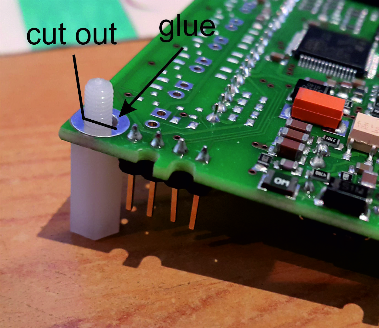
one picture is more valuable than thousand of words...
Just a random board to show the idea, plastic spacer glued:
|
73 Slawek
|
|
|
SP9BSL
positron
alter Hase
Offline
Posts: 443
|
|
Re:Aufbaubericht OVI40-UI Platine Version 1.8
« Reply #107 on: 17. January 2018, 07:57:14 »
|
|
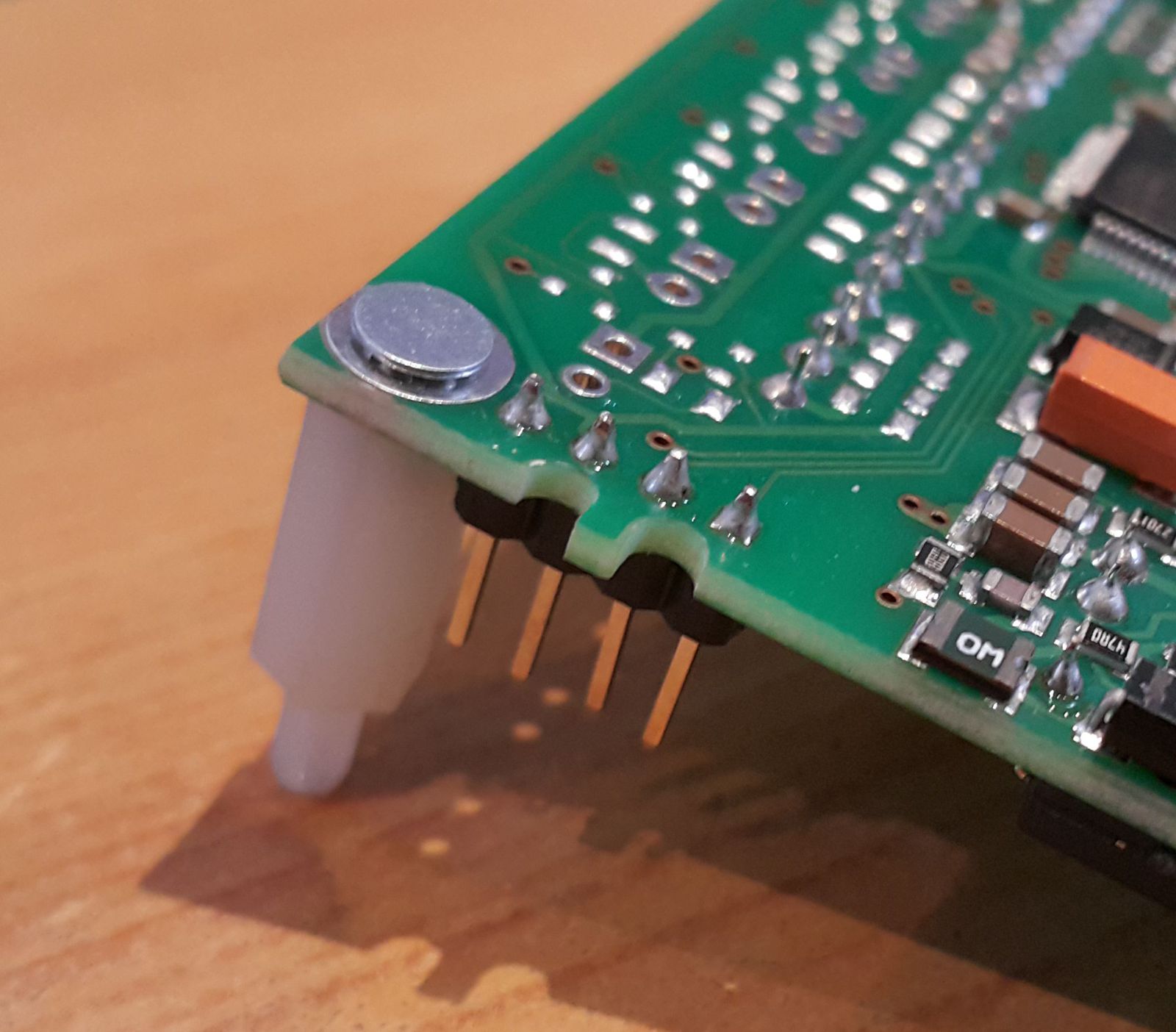
plastic spacer with PEM FH (sorry should be both internaly threaded spacer but I had only externally/internally one on the desk...)
|
73 Slawek
|
|
|
peter_77
Urgestein
Offline
Posts: 735

THE mcHF and UHSDR forum !

|
|
Re:Aufbaubericht OVI40-UI Platine Version 1.8
« Reply #108 on: 17. January 2018, 08:47:57 »
|
|
I just used a small piece of this 5mm white foam plastic which is mostly used in packaging. With a little bit standard glue under the left end opposite of the connector pins and thats it.
It has the advantage over spacers and hard plastic and also old capacitors that its a bit flexible. Later if you put all into a case it gently presses the display against the cutout window for a perfect finish.
|
|
 Logged Logged
|
|
|
|
SP9BSL
positron
alter Hase
Offline
Posts: 443
|
|
Re:Aufbaubericht OVI40-UI Platine Version 1.8
« Reply #109 on: 17. January 2018, 09:20:16 »
|
|
Hi Peter,
Yes the foam is a must somewhere between the lcd module and UI board. I use 1mm double adhesive foam between lcd and our lcd pcb. It is flexible enough to make the front metal case perfect fit to lcd. I think we should prepare a pdf with assembly instructions for the lcd, for everyone that just buys the lcd pcb alone.
|
|
Logged
|
73 Slawek
|
|
|
DL8EBD
positron
Urgestein
Offline
Posts: 1908
|
|
Re:Aufbaubericht OVI40-UI Platine Version 1.8
« Reply #110 on: 17. January 2018, 09:24:34 »
|
|
ja Peter und beim Touchen auf der linken Seite gibt das Display nach 
Bei der Beta V1.7 habe ich auch Schaumstoff untergelegt. Das drückt sich mit der Zeit platt...
Ich bin da eher für eine solide Lösung ala Slawek oder zumindest was massives unterlegen und festkleben.
|
| « Last Edit: 17. January 2018, 09:38:48 by DL8EBD » |
Logged
|
|
|
|
Michael_K
Urgestein
Offline
Posts: 638
Ich liebe dieses Forum!
|
|
Re:Aufbaubericht OVI40-UI Platine Version 1.8
« Reply #111 on: 17. January 2018, 10:40:32 »
|
|
ich habe aus einer 2-reihigen Buchsenleiste (wie die 34-polige) die Kontakte herausgezogen , unten und oben einen Streifen doppelseitiges Klebeband drauf; hält stabil und läßt sich bei Bedarf auch wieder lösen
Michael_K
|
|
Logged
|
|
|
|
|
|
DL8EBD
positron
Urgestein
Offline
Posts: 1908
|
|
Re:Aufbaubericht OVI40-UI Platine Version 1.8
« Reply #113 on: 21. January 2018, 19:11:58 »
|
|
so... ich kann dann auch den erfolgreichen Aufbau meiner V1.8 verkünden.
Ich hatte irgendwie das Pech den Uhrenquarz beim Material nicht zu finden und bin daher auf einen
Typ von Reichelt ausgewichen. Der lief aber nicht und somit konnte ich zwar den Bootloader flashen, das Board aber nicht starten. Kurz den Quarz aus der V1.7 ausgelötet - geht.
Woher an einem Sonntag einen 32kHz Quarz bekommen?
Ah, da liegt noch ein 32F746 Dico Board
Geht!
Sobald die zweite Batch anläuft bestelle ich noch einen Teilesatz und baue dann eine weitere UI V1.8 auf.
Die trägt dann den H7
Die "alte" UI Beta V1.7 werde ich dann später ausschließlich als VHF Gerät vollenden sobald die RF Baugruppe verfügbar ist.
Von meiner Seite gibt es keine zusätzlichen Auffälligkeiten zu erwähnen. Das einzig nennenswerte war die unpassende USB Buchse und die doch arg großen 1µF Kerkos.
Beides hatte ich noch am Lager....
Danke an Ralf für das überarbeitete Layout und danke an Andreas für die Materialzusammenstellung.
Und natürlich meinen Dank an allen die aktiv im Hintergrund werkeln. Allen voran natürlich Danilo und den Softwerkern
und einen ganz besonderen Dank nach Polen an Sławek für die Umsetzung des geilen 3,5" TFT
|
|
Logged
|
|
|
|
df9ts
positron
schon länger dabei
Offline
Posts: 73
Ich liebe dieses Forum!
|
|
Re:Aufbaubericht OVI40-UI Platine Version 1.8
« Reply #114 on: 22. January 2018, 20:45:07 »
|
|
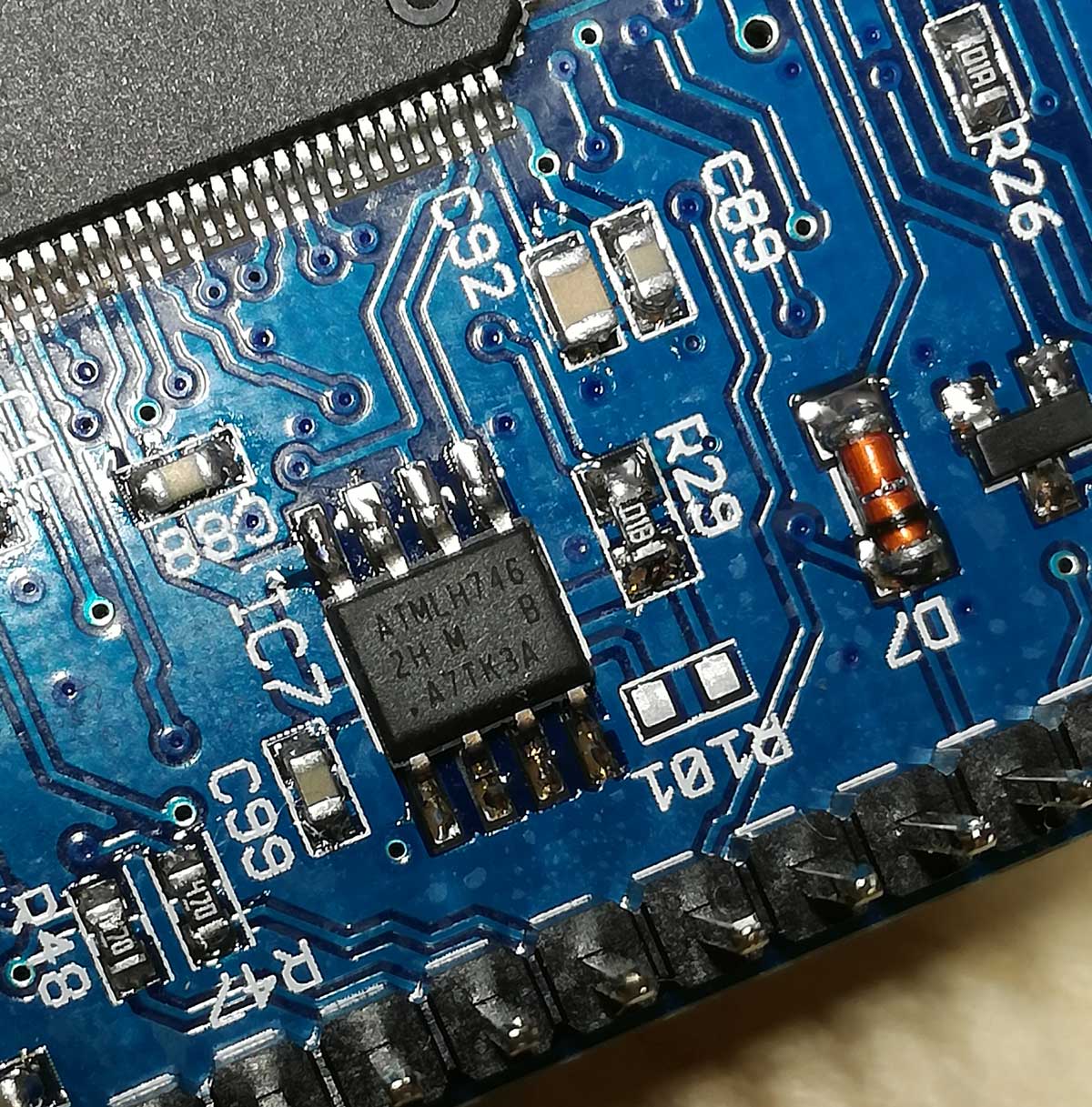
IC7 AT24CM02 EEPROM - wo ist Pin 1 
Wie ist denn der Pin1 markiert? Finde keinen Punkt auf dem Gehäuse, auch keine schräge Ecke?
ATMLH746
2H M B
.AT7k3A
Ist vielleicht der Punkt (der aussieht wie ein Teil der Beschriftung) der Pin 1?
73
Gerd.
|
|
Logged
|
|
|
|
|
|
DF9EH
alter Hase
Offline
Posts: 284
|
|
Re:Aufbaubericht OVI40-UI Platine Version 1.8
« Reply #116 on: 22. January 2018, 21:19:52 »
|
|
Hallo Gerd,
da ist ein kleiner Punkt 
Und eine Schräge ......
|
73 de Klaus
|
|
|
df9ts
positron
schon länger dabei
Offline
Posts: 73
Ich liebe dieses Forum!
|
|
Re:Aufbaubericht OVI40-UI Platine Version 1.8
« Reply #117 on: 22. January 2018, 21:29:23 »
|
|
Vielen Dank!
|
|
Logged
|
|
|
|
G4KCM
Neuling
Offline
Posts: 24

|
|
Re:Aufbaubericht OVI40-UI Platine Version 1.8
« Reply #118 on: 01. February 2018, 10:03:35 »
|
|
Construction complete, I have no new comment to add other than to echo the remarks previously made regarding component sizes. There seems to be plenty of ‘real estate’ on the PCB so it would be good to standardise on larger component sizes where possible.
The kit was complete and correct and ingeniously packed which along with the searchable layout pdf made the location of components quite easy. The only thing I needed to substitute was the mini USB which I already had in my component stock.
Have checked all that I can and the micro controller enters DFU mode so now the H7 patientialy awaits the firmware. If there is a ‘test’ load available I would be happy to try it.
Thank you to the team for the efforts in the development and documentation.
73
Clive
|
|
Logged
|
|
|
|
Co
schon länger dabei
Offline
Posts: 79
Ich liebe dieses Forum!
|
|
Re:Aufbaubericht OVI40-UI Platine Version 1.8
« Reply #119 on: 03. February 2018, 12:16:20 »
|
|
Hi Andreas,
Finished assembly UI board V1.08 this morning. Loaded bootloader and firmware 2.7.87 and bingo first try. No new problems encountered apart from those already reported.
Would also recommend switching to smd size 0805 to raise the fun level while assembling. Well done developers
73's
Co
|
|
Logged
|
|
|
|


 Author