Pages: 1 2 3 [4] 
|
 |
|
|
 Author
|
Topic: LCD 3.5" DF8OE/SP9BSL (Read 18686 times)
|
|
F4HTX
schon länger dabei

 Offline Offline
Posts: 66

Scotty, energize...

|
 |
Re:LCD 3.5" DF8OE/SP9BSL
« Reply #45 on: 18. February 2018, 13:38:51 »
|
|
Hi Slawek,
You are right isopropyl is a good friend. What is new for me here, is that it was working and faulty after a couple week of drying...
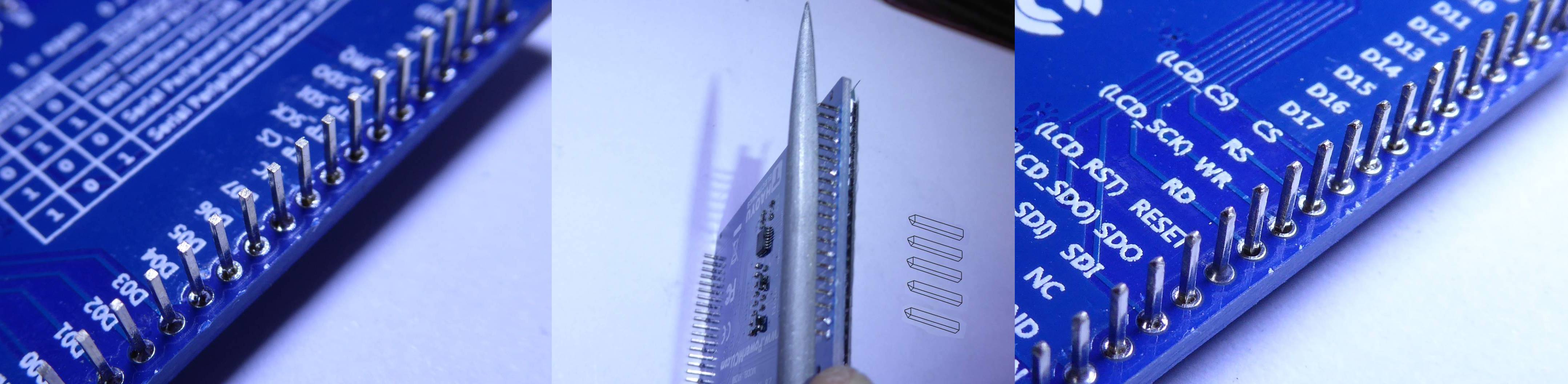
By the way about J103, cutting the end of the pins might not be the best idea as it damages the female connector each time it's inserted, by scraping it.
I would rather solder the pins at the right depth and then cut the pins flush to the pcb, in order to get the J103 pins undamaged, and so the female connector on the UI board.
73's
François
|
|
 Logged Logged
|
|
|
|
|
|
SP3OSJ
Guest

|
|
Re:LCD 3.5" DF8OE/SP9BSL
« Reply #47 on: 18. February 2018, 14:04:01 »
|
|
It has to be done
|
|
|
|
|
|
|
|
|
|
SP3OSJ
Guest
|
|
Re:LCD 3.5" DF8OE/SP9BSL
« Reply #51 on: 18. February 2018, 15:34:15 »
|
|
I will be happy if you want to use and copy something.
No problem.
|
|
Logged
|
|
|
|
Pages: 1 2 3 [4] 
|
|
|
|
|
|
|


 - but not absolutely correct.
