BO_Andy
Urgestein

 Offline Offline
Posts: 725

Ich bin schon Groß und kann Alleine Laufen
 
|
 |
Re:VisAir ddc modul und DSP PCBs Rolin
« Reply #45 on: 22. February 2020, 06:47:30 »
|
|
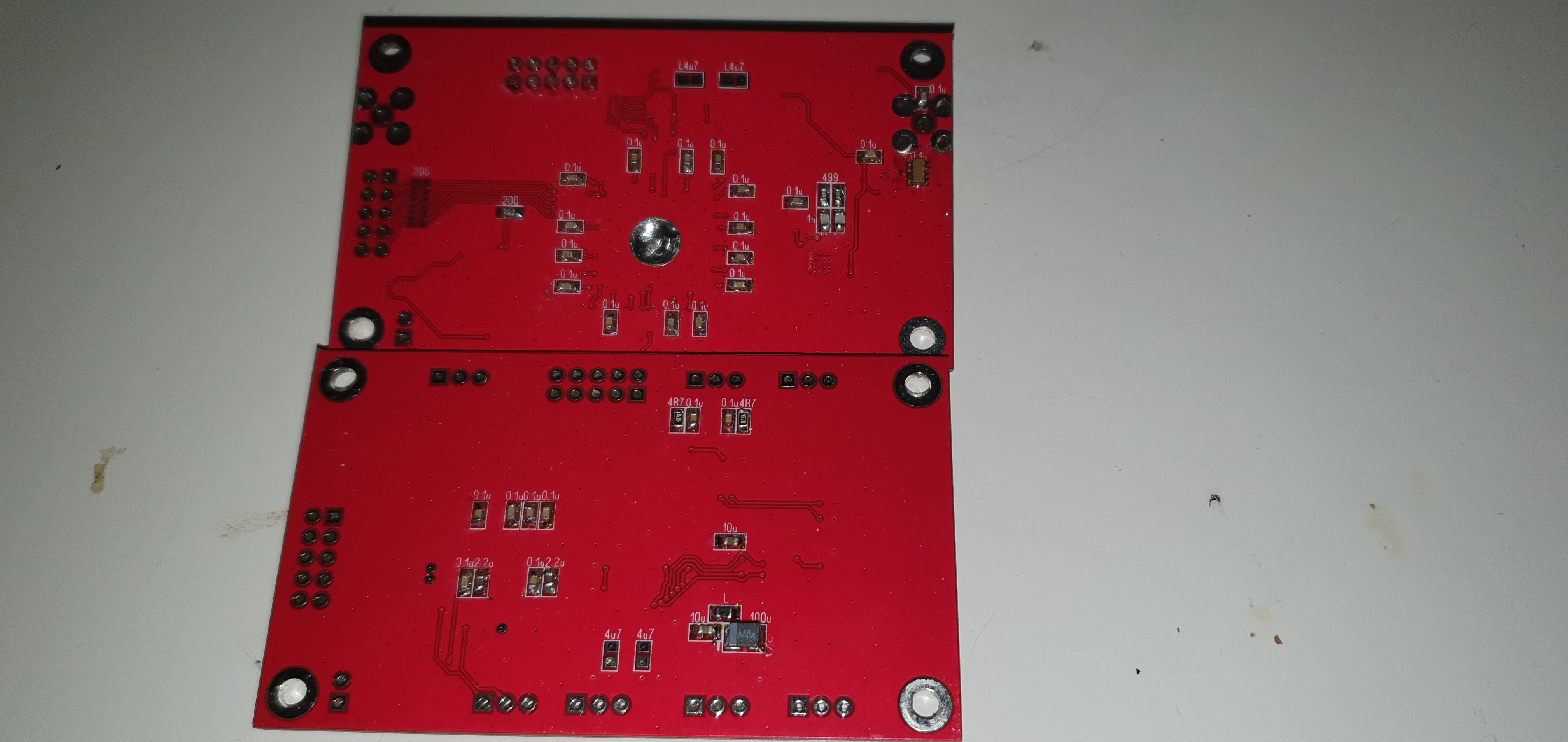
Und die Rückseite
|
|
|
|
BO_Andy
Urgestein
Offline
Posts: 725
Ich bin schon Groß und kann Alleine Laufen
|
|
Re:VisAir ddc modul und DSP PCBs Rolin
« Reply #46 on: 23. February 2020, 17:05:17 »
|
|
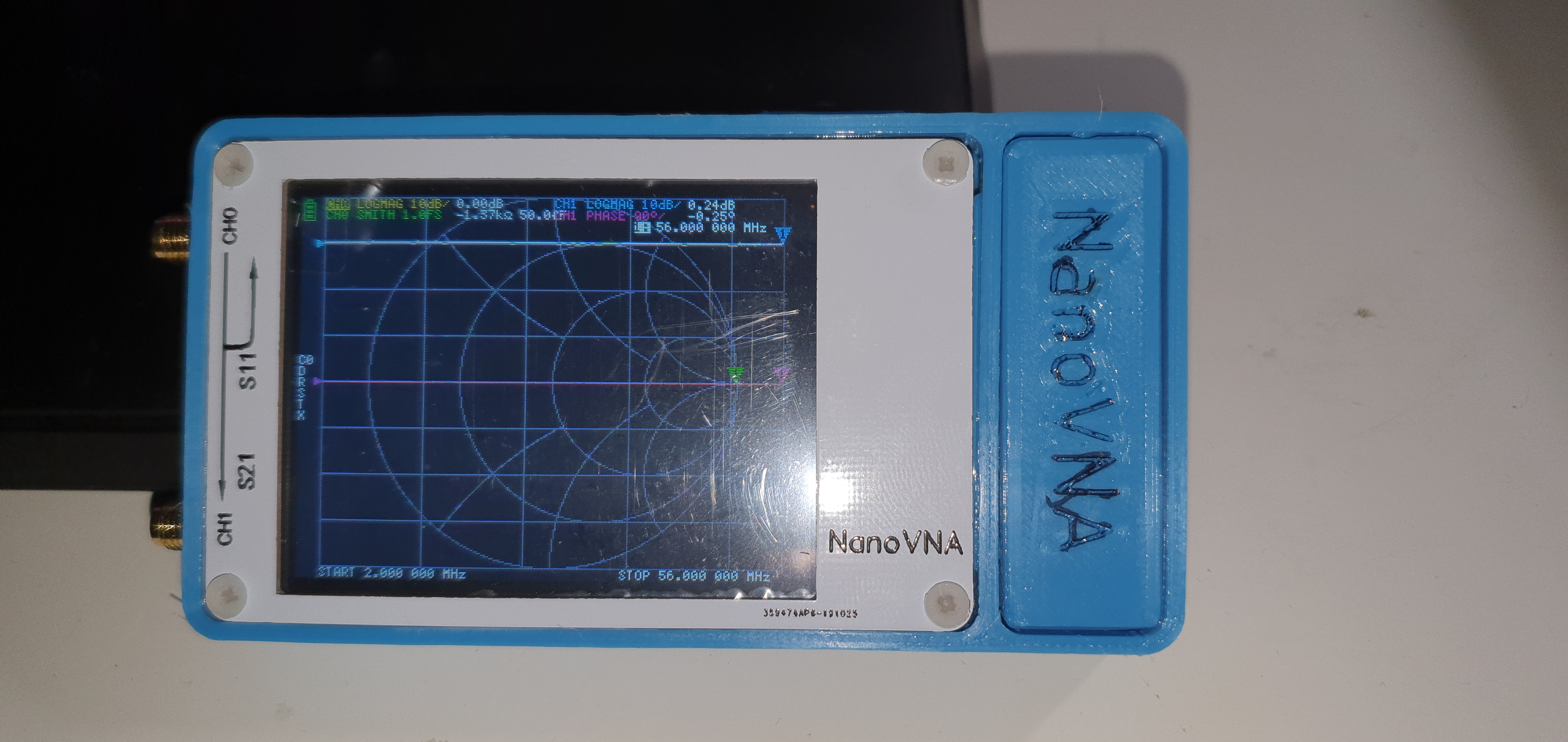
So ich habe gestern meinen VNA Nano bekommen und hoffe das ich damit Später die filter des DDC Module auf ihre Richtigkeit messen Kann.
|
|
|
|
|
|
BO_Andy
Urgestein
Offline
Posts: 725
Ich bin schon Groß und kann Alleine Laufen
|
|
Re:VisAir ddc modul und DSP PCBs Rolin
« Reply #48 on: 23. February 2020, 17:27:24 »
|
|
Ja Andreas ich habe mich deshalb dazu entschieden da es für denn filterberreich keinen bestückungsdruck gibt um es nochmal zu kontrollieren
|
|
 Logged Logged
|
|
|
|
BO_Andy
Urgestein
Offline
Posts: 725
Ich bin schon Groß und kann Alleine Laufen
|
|
Re:VisAir ddc modul und DSP PCBs Rolin
« Reply #49 on: 06. March 2020, 20:08:13 »
|
|
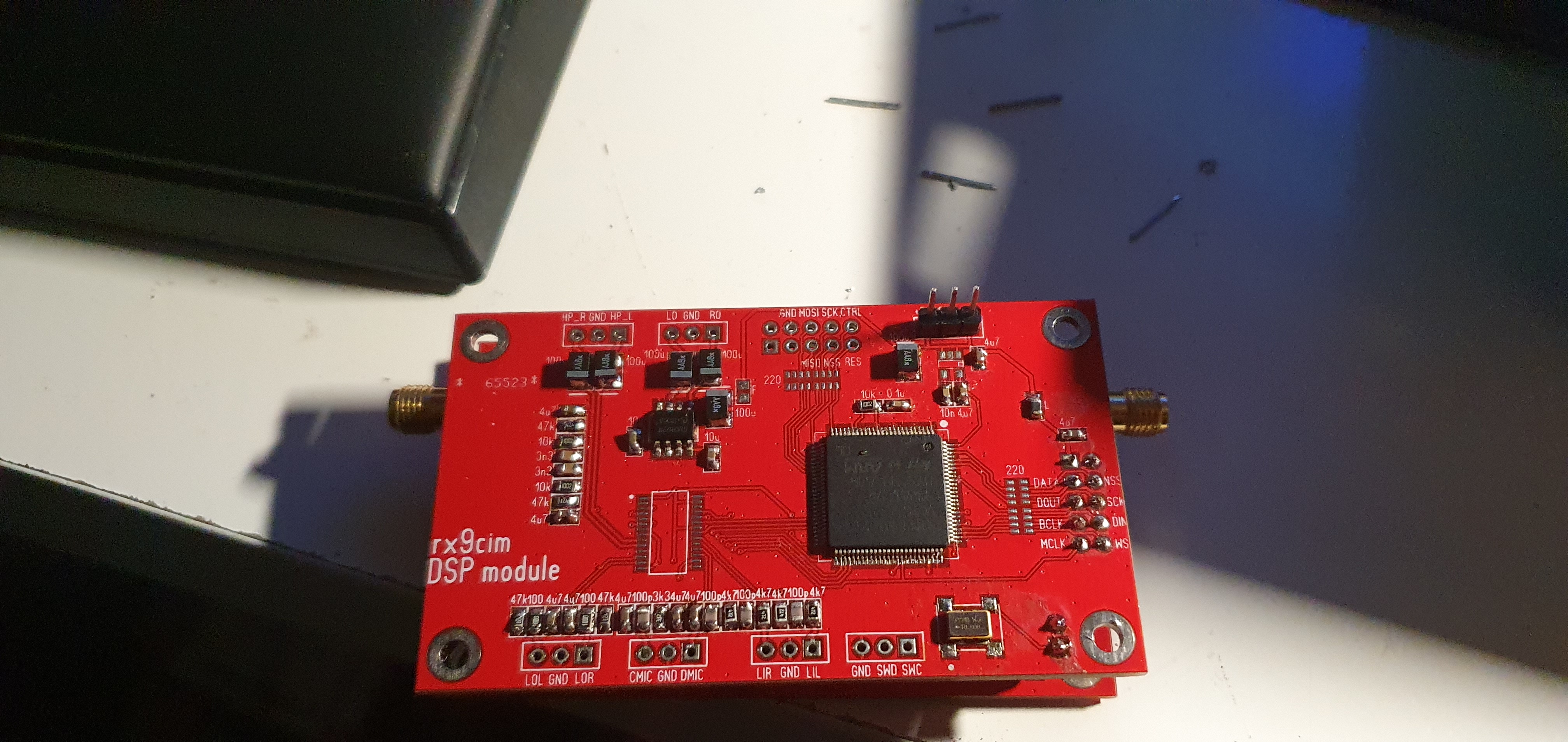
So es ist fast fertig leider fehlt mir der spannugsregler MCP1824T-3302E/OT noch wer einen Ersatz Typen weiss sende mir bitte einen Link
|
|
|
|
|
|
BO_Andy
Urgestein
Offline
Posts: 725
Ich bin schon Groß und kann Alleine Laufen
|
|
Re:VisAir ddc modul und DSP PCBs Rolin
« Reply #51 on: 07. March 2020, 16:11:18 »
|
|
So spannugsregler ist drauf aber irgendwas stimmt nicht stromaufnahme beträgt 220mA laut Rolin so diese bei 400 mA liegen heißt es fehlen irgendwo 180
Lg BO_Andy
|
|
Logged
|
|
|
|
|
|
BO_Andy
Urgestein
Offline
Posts: 725
Ich bin schon Groß und kann Alleine Laufen
|
|
Re:VisAir ddc modul und DSP PCBs Rolin
« Reply #53 on: 07. March 2020, 16:43:51 »
|
|
Andreas Es ist nur das DDC Modul mit der Firmenware drauf. Spannungen liegen auch an. Frage ist halt ob es letzten Endes an denn Refernes Quarz liegt
|
| « Last Edit: 07. March 2020, 16:46:20 by BO_Andy » |
Logged
|
|
|
|
|
|
BO_Andy
Urgestein
Offline
Posts: 725
Ich bin schon Groß und kann Alleine Laufen
|
|
Re:VisAir ddc modul und DSP PCBs Rolin
« Reply #55 on: 07. March 2020, 17:34:46 »
|
|
Das könnte auch sein man müsste mal probieren über spi byts zu senden da das modul ja als Slaven läuft und nicht als Master. Ich bin grade am überlegen ob ich meinen arduino dafür nutze
|
|
Logged
|
|
|
|
|
|
BO_Andy
Urgestein
Offline
Posts: 725
Ich bin schon Groß und kann Alleine Laufen
|
|
Re:VisAir ddc modul und DSP PCBs Rolin
« Reply #57 on: 08. March 2020, 16:02:55 »
|
|
Ich habe bald denn 122.88 MHz quarz in Vermutung da ich dort einen anderen drin haben. Denn NV7050SA
|
|
Logged
|
|
|
|
BO_Andy
Urgestein
Offline
Posts: 725
Ich bin schon Groß und kann Alleine Laufen
|
|
Re:VisAir ddc modul und DSP PCBs Rolin
« Reply #58 on: 10. March 2020, 21:26:42 »
|
|
Mal eine frage ich was muss ich die zahlen umrechen nehmen wir mal an das Modull soll mit 55MHz laufen. Die sollen in 4 Btys Dagestellt werden was 4 stellen wären und in bit 32 .
Lg BO_Andy
|
|
Logged
|
|
|
|
DL8EBD
positron
Urgestein
Offline
Posts: 1926

|
|
Re:VisAir ddc modul und DSP PCBs Rolin
« Reply #59 on: 11. March 2020, 06:10:34 »
|
|
Hallo Andy,
ich bin da nicht im Stoff, aber ist es nicht so:
Bit assignment:
// SPI Module, Slave, 11 Bytes, MSB is first
// 32b Rx_freq 32b Tx_freq 8b ATT 8b Tx_level 6b 0, 2b S_Rate
// | ________________ || ________________ || ___________ || ____________ || ________________ |
// 87 56 55 24 23 16 15 8 7 0
//
// DATA --- / 8bit / --- / 7bit / --- / 6bit / --- / 5bit / --- / 4bit / --- / 3bit / --- / 2bit / --- / 1bit / --- / 0bit / ---------
// CLK _____ | ---- | ____ | ----- | ___ | ---- | ___ | --- | ____ | ---- | ___ | --- | ____ | --- | ____ | --- | ____ | ---- | ______
// EN ___________________________________________________________________ | - - | ___
// or
// EN --- | _________________________________________________________________ | --------
The first 4 bytes contain the value of the receiver tuning frequency in Hertz, the next 4 bytes contain the same value for the transmitter.
The next byte is the attenuator value, from 0 to 30, followed by the transmitter output power level byte, from 0 to 255.
The last byte controls the sample rate of the output data. The highest 6 bits are not used and should be set to 0. Depending on the state of the lower two bits, the corresponding sample rate is set, if 00, then 48 kHz, 01 - 96 kHz, 10 - 192 kHz.
When choosing a sample rate of 96 or 192 kHz, the data for the transmitter also has to be transmitted at the same speed, since the I2S bus is shared, but in fact the transmitter always works at a data rate of 48 kHz. To run the bus at higher speeds, you simply need to duplicate the samples.
|
|
demnach muss man 55MHz als 55.000.000 Hz betrachten.
Hexadezimal: 0347 3BC0
Binär: 00000011 01000111 00111011 11000000
|
| « Last Edit: 11. March 2020, 06:44:24 by DL8EBD » |
Logged
|
bitte keine technische Fragen oder Diskussionen via PN, dafür ist das Forum da.
vy73
Thomas
|
|
|


 Author