This is an old revision of the document!
UI Board Test & Trouble Shooting
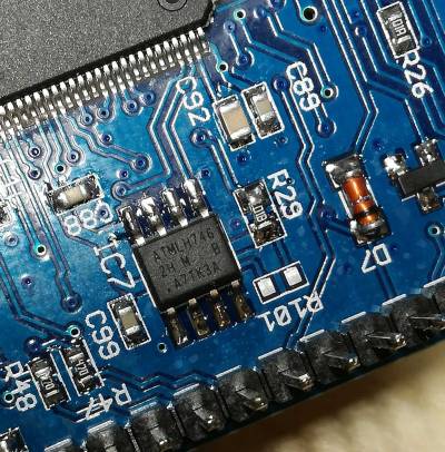
EEPROM IC7 Pin 1 orientation
This is where the dot is printed. Also the edge of the case is slanted near the 1-4 pins. See here
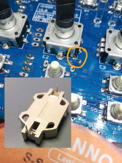
Potential short cut next to battery holder
Note: Also ganz wichtig: Wie auf dem Bild zu sehen unbedingt den einen Anschlußpin vor dem Einbau kürzen/abschneiden.
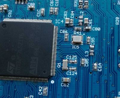
Attention: STM32 MCU Pin1 Mark
The MCU seems to have two (!) pin 1 marks. Watch text orientation on MCU to find “real” pin 1.
Missing Audio out
In case of missing audio out: just in case, please check the SW_12V connection. This is power supply connector for Audio power amplifier stage unlike the mcHF.
Typical current consumption
Typischer Stromverbrauch: mit Display 280mA und ohne Display sind es 190mA. Die 80mA waren ohne Display direkt nach der Inbetriebnahme.
In case of problems to flash the MCU
- RTC clock crystal and TXCO are prerequisite for flash programming to work
- Check correct orientation of TXCO (see photo on this page)
- Check 3.3V at C95. If not present then L3 may be defective
LEDs too bright
With the kit resistors the LEDs are quite bright. DF9EH has reduced the values as follows:
- R36 22k6 (D1 green)
- R37 6k8 (D2 red)
- R116 6k8 (D3 blue)
"WM8731 not detected"
In case you see this UHSDR error message please check +3V supply for codecs (WM8731) is ok. This +3V supply is generated on RF board.
MCU läuft gar nicht, auch DFU Verbindung geht nicht
Zuerst prüfen, ob die MCU in korrekter Lage eingelötet wurde (“Pin 1”).
Nach dem booten legt die MCU 3.3V an die Taster. Um erfolgreich zu booten braucht die MCU:
- CPU Takt (→ TXCO Takt messen)
- Korrekten Spannungsreset (→ Spannungsverlauf und Spannungspegel am Reset Pin messen)
Falls dies der Fall ist, funktioniert Ansprechen über ST-Link Adapter und gesetzten Junper P6 im “DFU” Modus.
Buttons, LEDs und LCD sind da noch nicht initialisiert. Erst wenn der Bootloader installiert wurde und läuft hat man minimalistisch die Peripherie-GPIOs initialisiert, d.h. einige (!!) Buttons und das LCD sowie die LEDs und je nachdem welchen Button man beim Einschalten drückst die große ODER die kleine USB-Schnittstelle.
Bei installiertem Bootloader:
- Taste “Band -” drücken, dann OVI40 UI board hochfahren ⇒ große USB Buchse aktiviert für Firmwareupdate via USB Stick
- Taste “Band +” drücken, dann OVI40 UI board hochfahren ⇒ Boot Loader Update via kleine USB Buchse
Prüfen:
- erkennt der PC das per USB angeschlossene OVI40 UI board (Gerätemanager / Device Manager)?
- PC USB port working? USB cable ok?
- Check all MCU pins are correctly soldered and no shortcuts exist: Use a thin knife / scalpell / tweezer, go inbetween MCU pins and try to push the pins gently sideways one by one, check if all are soldered to PCB. If not the pin moves slightly.
NF Audio Verstärker geht nicht
Bitte +12V Versorgung des NF Audio Verstärkers messen. Er wird vom OVI40 RF Board über JP1 versorgt.
USB Stick funktioniert nicht
Bitte +8V Versorgung von RF Board prüfen, JP1.


