Pages: [1] 
|
 |
|
|
 Author
|
Topic: The DDC board (Read 2602 times)
|
|
SP9BSL
Moderator
positron
alter Hase

 Offline Offline
Posts: 443

 
|
 |
The DDC board
« on: 30. June 2020, 09:32:40 »
|
|
Hi,
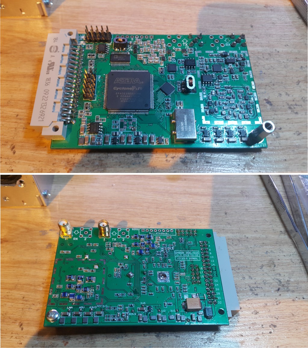
the DDC board is the main RF interface of my project. The main task of this board is to convert the RF analog signal to digital equivalent and transmit it via I2S/SAI port to F7/H7 core and provide clocking for all the data processing chain. At the HF input of the receiver i placed the variable attenuator (0..31.5dB) and antialiasing filter for lower bands up to 6m. This is conventional part of DDC receiver working in first Nyquist zone with frequencies below half of the sampling rate. The second input is provided for 4m and 2m support based on 2nd and 3rd Nyquist zone, so called 2nd and 3rd aliases. To make it works a set of band pass filters is needed - also on the board. At the input I've placed the LNA (PGA103+) for higher than 6m bands which is not good solution for lower bands because of large impedance mismatch. The transmitter path uses exactly the same type and count of the filters - just second set because this board is full duplex.
Beside this RF circuit board has low phase noise clock with additional precise frequency TCXo to form a kind of frequency locked loop (long term), done digitally in FPGA. All the I/O transactions go by SPI interface directly to the F7/H7 core in UI. The board was designed as 4 layer board to keep the impedances and shield where it is necessary. The dimensions: 91x60mm. Almost all board component size is 0603 with some 1206.
|
73 Slawek
|
|
|
SP9BSL
Moderator
positron
alter Hase
Offline
Posts: 443
|
|
Re:The DDC board
« Reply #1 on: 30. June 2020, 09:33:22 »
|
|
Some measurements of the input:
|
73 Slawek
|
|
|
SP9BSL
Moderator
positron
alter Hase
Offline
Posts: 443
|
|
Re:The DDC board
« Reply #2 on: 01. July 2020, 11:58:03 »
|
|
Corrected wrong file of the output signal:
|
73 Slawek
|
|
|
Pages: [1] 
|
|
|
|
|
|
|


 Logged
 Single_tone_measurements.pdf