Author
|
Topic: LCD Kit OVI40 Vers.V1.2 (Read 11927 times)
|
|
peter_77
Urgestein

 Offline Offline
Posts: 735

THE mcHF and UHSDR forum !


|
 |
Re:LCD Kit OVI40 Vers.V1.2
« Reply #45 on: 02. February 2019, 17:08:27 »
|
|
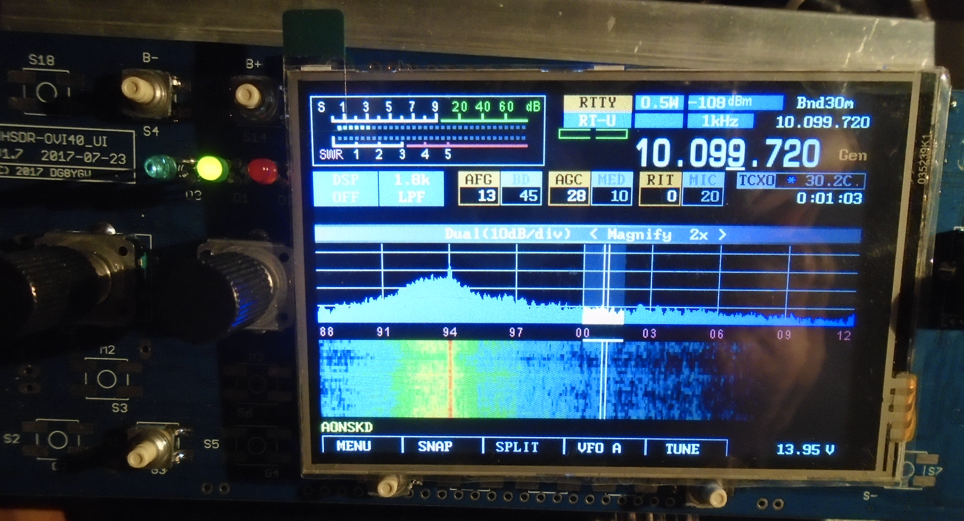
Spielt auf Anhieb and works like a charm... 
Nach etwas graben auf dem Schreibtisch hatte ich dann auch den Bestückungszettel wiedergefunden.
Etwas gemein war ja C104 und C105. Du hast sie genau umgedreht zum Bestückungszettel bestückt.
Macht man es nach Zettel muss dann aber der Tantaler gedreht werden von der Polarität. Ein Glück das ich das alles nochmal mit dem Ohmmeter durchgeklingelt habe vor dem richtigen Festlöten. 
|
 lcdok.png lcdok.png
« Last Edit: 02. February 2019, 17:12:19 by peter_77 » |
 Logged Logged
|
|
|
|
DF5LI
alter Hase
Offline
Posts: 371

Ich liebe meinen SParrow !
|
|
Re:LCD Kit OVI40 Vers.V1.2
« Reply #46 on: 02. February 2019, 19:31:10 »
|
|
Ein zu großer C103 kann dazu führen, dass der Spannungsregler IC 101 beim Abstecken des Diplays bei laufendem Betrieb invers betrieben wird, also am Ausgang liegt Spannung an, am Eingang nicht. Das mögen manche Regler garnicht. Aber im eingeschalteten Zustand sollte man das Display sowieso nicht abstecken. Auf der ganz sicheren Seite ist man aber nur, wenn der C weggelassen wird oder über den Ein- und Ausgang eine Schutzdiode kommt. Das sind aber wohl mehr theoretische Erwägungen...
Ich suche gerade nach den Forumseinträgen zum Maximalstrom für das LCD-Backlight, aber irgendwie funktioniert die Suchfunktion nicht. Kann mir da jemand weiterhelfen ?
|
| « Last Edit: 02. February 2019, 19:41:33 by DF5LI » |
Logged
|
73, Harri
|
|
|
|
|
DF5LI
alter Hase
Offline
Posts: 371
Ich liebe meinen SParrow !
|
|
Re:LCD Kit OVI40 Vers.V1.2
« Reply #48 on: 02. February 2019, 21:45:34 »
|
|
Vielen Dank, Slawek !
Ich denke, mit 7,5 Ohm für R 105 bin ich auf der sicheren Seite.
|
| « Last Edit: 02. February 2019, 21:46:18 by DF5LI » |
Logged
|
73, Harri
|
|
|
peter_77
Urgestein
Offline
Posts: 735
THE mcHF and UHSDR forum !
|
|
Re:LCD Kit OVI40 Vers.V1.2
« Reply #49 on: 03. February 2019, 11:30:53 »
|
|
The last kit from Andreas has 2,2 ohms for R105.
Btw. i used 68µF for C103. Hopefully thats acceptable? Of course i would never unplug the live LCD under power.
|
| « Last Edit: 03. February 2019, 11:31:20 by peter_77 » |
Logged
|
|
|
|
SP9BSL
positron
alter Hase
Offline
Posts: 443

|
|
Re:LCD Kit OVI40 Vers.V1.2
« Reply #50 on: 03. February 2019, 11:59:40 »
|
|
Hi Peter,
as I said it depends on LCD module, if your lcd has no noticeable warm up - it is OK.
Regarding the capacitor, I recommended the 100u but the truth is if you use anything equal or above 22u (X7R, X5R) will work. This capacitance is for blocking the dimming current.
|
| « Last Edit: 03. February 2019, 12:00:19 by SP9BSL » |
Logged
|
73 Slawek
|
|
|
peter_77
Urgestein
Offline
Posts: 735
THE mcHF and UHSDR forum !
|
|
Re:LCD Kit OVI40 Vers.V1.2
« Reply #51 on: 03. February 2019, 12:23:30 »
|
|
Cześć! Slawek !
OK, sounds good. I could'nt notice any bigger warmup so i guess its ok. I also count on Andreas here, cause i assume he has tested that waterproof with the provided displays of his own kits ?!
On the other hand Andreas used in his ready made 3.5" displays a resitor labled "150" for R105 which i assume is 150 ohms !
A value which is pretty far away from 2R2 or even 4R7.
The display panels itself look pretty much the same, so there are still some doubts why we have such a huge difference here...?? 
Hopefully the 2R2 will not kill the LCD in a long term usage perspective..?!
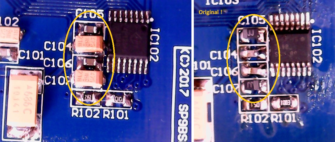
Btw. here is the difference of C104 and C107 from the kit list and the ready assembled ones. You need to keep an eye here on the tantalum C104 and C107 polarity !
|
C104-107.jpg
« Last Edit: 03. February 2019, 12:39:42 by peter_77 » |
Logged
|
|
|
|
SP9BSL
positron
alter Hase
Offline
Posts: 443
|
|
Re:LCD Kit OVI40 Vers.V1.2
« Reply #52 on: 03. February 2019, 13:00:39 »
|
|
no, resistor labeled 150 is 15ohm, last digit means ten multiplier like in ordinary thru hole resistors
|
|
Logged
|
73 Slawek
|
|
|
peter_77
Urgestein
Offline
Posts: 735
THE mcHF and UHSDR forum !
|
|
Re:LCD Kit OVI40 Vers.V1.2
« Reply #53 on: 03. February 2019, 13:30:42 »
|
|
Sorry, yes you are right with 15 Ω.
But anyway, its still a huge difference to the provided 2R2 in the kit !
|
| « Last Edit: 03. February 2019, 13:32:54 by peter_77 » |
Logged
|
|
|
|
|
|
peter_77
Urgestein
Offline
Posts: 735
THE mcHF and UHSDR forum !
|
|
Re:LCD Kit OVI40 Vers.V1.2
« Reply #55 on: 04. February 2019, 08:16:36 »
|
|
As a conclusion is it then safe to replace the existing 15Ω on R105 on your older, ready assembled displays with the new value 2,2Ω ?
Or maybe as a compromise with 4,7Ω cause i still have this value as a leftover from the I40 and SParrow assembly.
|
| « Last Edit: 04. February 2019, 08:18:02 by peter_77 » |
Logged
|
|
|
|
|
|
DF5LI
alter Hase
Offline
Posts: 371
Ich liebe meinen SParrow !
|
|
Re:LCD Kit OVI40 Vers.V1.2
« Reply #57 on: 04. February 2019, 15:13:32 »
|
|
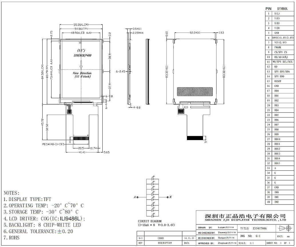
Soo, ich habe endlich ein Datenblatt für das Display gefunden. Da findet sich eine Angabe über das Backlight: 8 x 15 mA parallel. Also wäre ein Strom von 120 mA noch innerhalb der Spezifikationen. Dann kann ich ja mit gutem Gewissen einen 2,2 Ohm Widerstand verwenden und mich über die Helligkeit freuen 
|
73, Harri
|
|
|
|
|
SP9BSL
positron
alter Hase
Offline
Posts: 443
|
|
Re:LCD Kit OVI40 Vers.V1.2
« Reply #59 on: 04. February 2019, 17:02:12 »
|
|
Hello all,
Harri, may I ask you to measure the voltage on LEDs with 2R2 resistor?
|
|
Logged
|
73 Slawek
|
|
|
|
|
|